


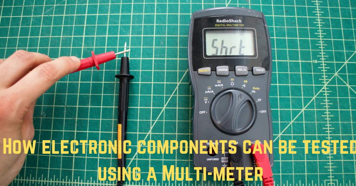
How to use a multimeter and how to test electronic components with a multimeter
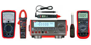
A multimeter can be used to test electronic components, and there are two different types of multimeters: digital and analogue. While inspecting an electronic component, the analogue multimeter has a pointer to indicate the value, whereas the digital multimeter displays values that number. Analog and digital multimeter images can be seen in the image below. The majority of multimeters include rotary selectors, which allow us to choose the function and range. For example, if we need to examine a resistor, we can use a rotary selector to alter the function and range to the necessary ohms.
In order to correctly test any electronic component, we must be able to use a multimeter. Therefore, we must be aware of certain factors before measuring anything. For example, if we need to check the voltage, we must choose an AC or DC range depending on the power source, and if we need to check the resistance, we must choose an ohms range. The most crucial consideration when using a multimeter is to set the range of voltage and current to the maximum value. An overload is indicated by an OL in a digital multimeter, so if we see one while testing, we should be aware that the source we measured was above the limit we had set.
How to Examine Resistors
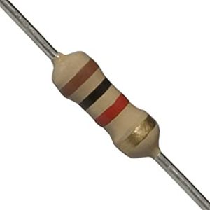
A resistor is a component that can resist or reduce the current flowing through a wire. Ohm’s law is used to calculate the qualities of resistance. Every resistor has a colour code, and the colour code describes the resistance of the resistor. The necessary voltage drop will be possible to provide with a resistor. Set the ohm’s scale and then set the range approximately to your assumption value based on the colour code and the resistance, the resistance range should not be set too low.
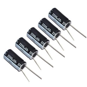
How to Examine Capacitators
A capacitor is a passive component that contains a dielectric that separates two conductors. It must be discharged before checking the capacitors. To check the capacitor, select the resistance range in the multimeter and connect the multimeter leads to the capacitor terminals. The reading will be extremely low if the capacitor is damaged. However, when we connect the leads of the multimeter to certain types of capacitors, such as electrolytic capacitors, the resistance will initially be low and then increase, indicating that the capacitor is in good condition.
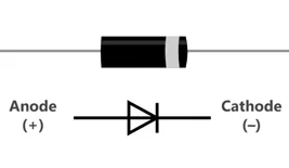
How to Examine Diode
Diodes are made of semiconductor material and consist of two parts: anode and cathode. The anode is the positive section, and the cathode is the negative section. A diode has a high resistance in one direction and a very low resistance in the other. To test the diode, connect the multimeter leads to the diode terminal and check the forward and reverse biased conditions to see if the diode works. So, if the diode has low resistance when forward-biased and high resistance when reverse-biased, it is operational.
How to Examine Transistor
Transistors are active electronic components that can be used for amplification as well as switching. The majority of transistors are made of silicon or germanium. Set the resistance range in the multimeter to test the transistor. Connect the multimeter probes to the transistor, with the positive section of the multimeter connected to the emitter section and the base of the transistor connected to the negative section of the multimeter. In this case, we might get readings like low resistance for forward bias and high resistance for reverse bias. If the transistor is damaged, the resistance between any two terminals will be less than 10 ohms.
![]()
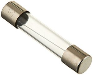
How to Examine a Fuse and a Coil
To test the fuse and coil, set the multimeter to the resistor range and connect the multimeter leads to the fuse, if there is no reading, the fuse is damaged. Repeat for the coil, and if there is no reading, it is damaged.
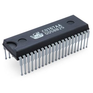
How to Examine IC’s
Integrated circuits (ICs) contain resistors transistors and diodes. It is extremely difficult to test the IC. Set the multimeter to continuity, connect the red lead to the IC’s ground, and check it with the black lead. So, while doing this, we would get readings and, in some cases, we would hear a sound from the multimeter, which indicates that the IC is damaged. An IC’s temperature can also be checked; if the IC is heating up quickly, it is damaged.
Conclusion
Making an electronic device is a challenging task, isn’t it? If you are not sure which parts to use or how many of each part you require. Do not worry, Escronics is ready to assist you. We have every electronic component you can think of for any project you can think of. Simply look through our website and contact any of our suppliers. Begin immediately!